
 |


Built around a conservator tank and plate radiators, the 800kVA oil immersed transformer is a three-phase oil immersed distribution transformer that marks the point where full oil protection and cooling accessories become standard. Taking 10kV or 35kV on the primary side and supplying 0.4kV, the oil immersed unit is used in industrial substations, water and sewage treatment plants, rail depots and large warehouses that depend on motor driven loads.
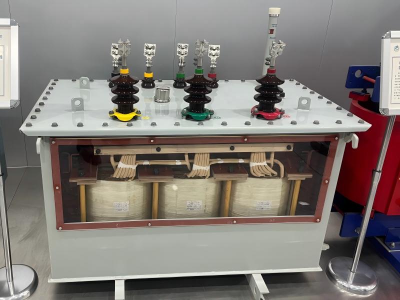
Structurally the oil filled transformer is equipped with a conservator, plate radiators, a gas relay, a pressure relief valve and a silica gel breather, together with a cold rolled silicon steel sheet core and high strength insulated windings. An on-load tap changer can be fitted when the supply voltage varies during the day. Its overall performance conforms to GB 1094 and GB/T 6451 series standards, and to IEC 60076 for overseas markets.
| Electrical | Rated Capacity | 800kVA |
Voltage | 2.4-34.5 kV - 480/277V 400/230V 380/220V Customized | |
Frequency | 50/60Hz | |
Vector Group | Dyn11, Yyn0, Dyn5 or customized | |
H.V. Tap Changer | ±2×2.5% HV taps or customized | |
Efficiency | As IEEE, DoE 2016, GB or Customized | |
Impedance Voltage | 1.1-5.75% | |
Cooling Method | ONAN, ONAN/ONAF, KNAN, KNAN/KNAF | |
| Physical & Standards | Total Weight | 3500 kg |
Outline Dimensions(L×W×H) | 1620 × 880 × 1520 mm | |
Standards/Certificate | IEEE, UL, ISO, IEC, GB | |
Altitude | ≤1,000m, 1000–2000m, 2000–3000m, >3000m | |
| Material | Transformer Oil | Mineral Oil or FR3 |
Winding Material | Aluminum/Copper | |
Core Material | CRGO Silicon Steel / Amorphous Alloy | |
Tank Material | Mild Steel / Stainless Steel |
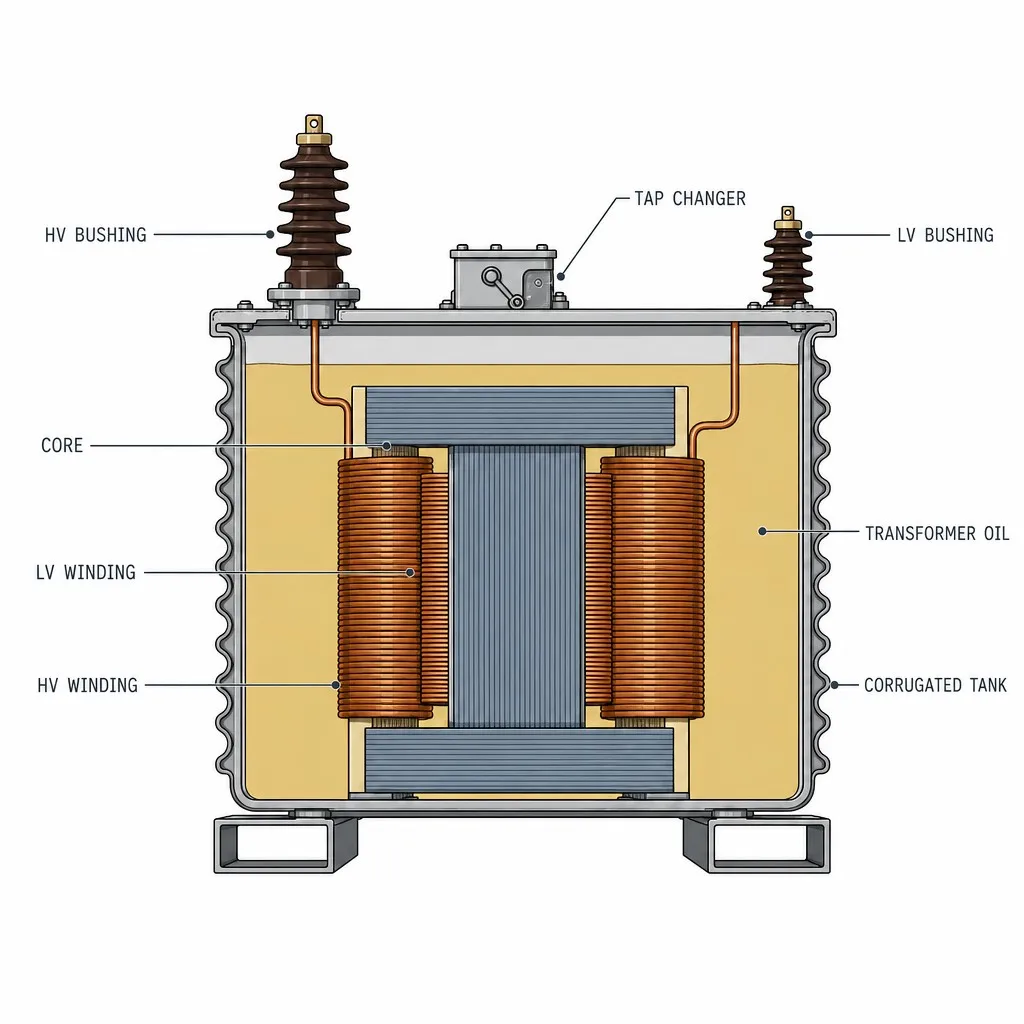
It is located in the center of the active part and is made of stacked or wound cold-rolled grain-oriented silicon steel sheets to form a closed magnetic circuit. Joints are mitered at 45° with clamps and a single point ground to minimize no-load losses and noise, and for safety reasons.
The winding, inner or outer, closest to the core limbs. Due to the high current on the 0.4 kV side, the windings are usually of the foil type (copper or aluminium). The axial distribution of ampere turns is uniform. The short circuit withstand capability is high.
The outer winding which is placed concentrically with the LV winding. The 10 kV side is a multilayer cylinder construction with insulation and oil ducts in between the layers. It is separated from the LV winding by composite oil-paper main insulation.
Fills the tank and immerses the active part. It has three functions: insulation (increasing the dielectric strength between windings and to ground), heat dissipation (removing heat to the tank walls by natural convection), and protection against moisture (isolating air to slow down aging of the insulation).
It is the transformer enclosure and the radiator also. The tank walls are corrugated. The corrugated panels are completely sealed so that they can elastically compensate the volume changes of the oil due to temperature variations. The oil does not touch the outside air and is therefore maintenance-free.
This is mounted on the tank cover and provides safe termination of the leads of the HV winding out of the tank. It provides 10 kV insulation to ground and mechanical support for cable or busbar connections.
It is mounted on the other side of the tank cover and brings out the three phase and neutral leads for the 0.4 kV side. It does the same insulation and lead out functions as the HV bushing but is smaller in size.
Off-circuit type, mounted on the tank cover operating mechanism and connected to the HV winding taps. It has a normal ±2×2.5% tap range and is manually set to the local voltage levels while de-energized.
Every transformer is tested before shipment according to applicable standards and customer requirements — from the first batch of raw material to the final routine test on the factory floor.
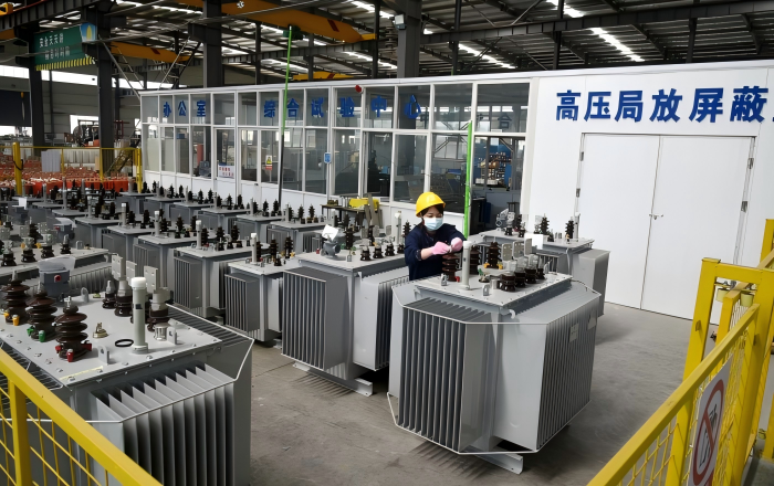
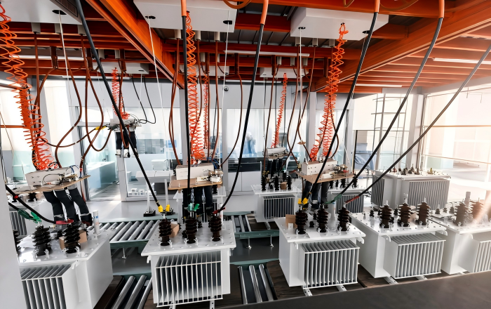
Transformer quality begins with the materials we bring in. Every batch of incoming material is inspected against approved specifications before production, with supplier qualification and traceability records maintained for each shipment.
Progress tests are conducted at key stages of the manufacturing process to verify that every 800kVA three-phase oil-immersed transformer meets design and quality requirements before final assembly.
Before leaving the factory, each transformer undergoes routine testing — conducted in accordance with GB 1094 / IEC 60076 standards — covering key parameters such as insulation resistance, winding DC resistance, voltage ratio and vector group, no-load loss and current, load loss and short-circuit impedance, and applied voltage withstand.
Upon successful completion of all tests, the unit is shipped with a factory test report and a certificate of conformity, ensuring that every delivered product meets its rated performance and safety specifications.
800kVA Oil Immersed Transformers are available with a range of configurable options to meet different electrical and environmental requirements. Customers can select the appropriate insulating medium, voltage configuration, protection devices and accessories according to their specific project conditions.
For projects with higher environmental and fire-safety requirements, ester-based insulating fluids such as FR3 can be selected as an alternative to conventional mineral oil. These fluids offer a higher fire point and good biodegradability, making them suitable for applications where environmental protection and installation safety are important considerations.
The transformer can also be equipped with suitable voltage regulation and protection solutions, including load switching devices, surge protection, fuses and temperature monitoring components. These options allow the transformer to be configured for different grid conditions, load characteristics and protection requirements.
From utility distribution and commercial facilities to industrial and renewable energy projects, flexible transformer configurations help customers achieve the required balance of electrical performance, operational safety and environmental compliance.
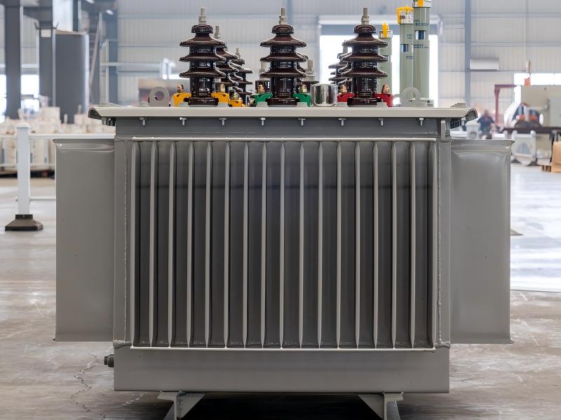
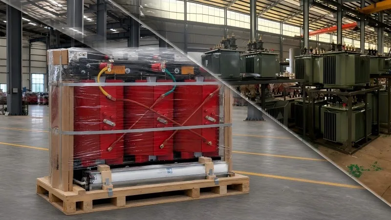
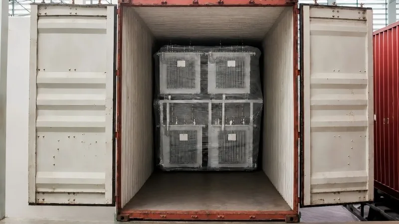
We ensure every three-phase oil-immersed transformer is safely packed, securely transported, and ready for installation.
Secure Packaging: Weather-resistant wooden crates or steel containers protect against moisture, vibration, and impact.
Complete Accessories: Standard accessories are factory-installed and tested, while optional components are packed separately.
Reliable Transport: Road, rail, or sea shipping is arranged according to project requirements.
Complete Documentation: Test reports, certificates, manuals, and shipping documents are provided.
Installation Support: Unpacking, installation, and commissioning guidance is available for smooth project delivery.
Watch for these common signs:
The essential parameters for a quote or order:
A distribution transformer is the final voltage-conversion device between the utility distribution network and the end user. It steps down medium distribution voltage to the low voltage used by homes, businesses and industrial equipment (e.g. 120/240 V, 480 V, 600 V).


