
 |

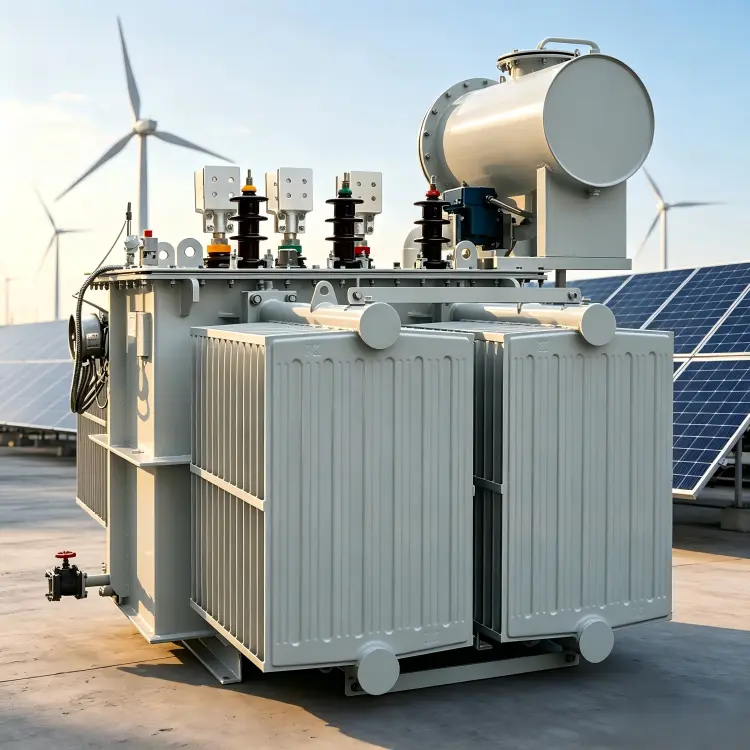



A compact substation for new-energy plants collects the inverter or turbine output and steps it up to the collection voltage. It is specified for solar and wind farms where ground is tight or the plot is shared, and for rural electrification and utility generation blocks. High voltage and low voltage rooms sit in separate compartments so switching work stays independent of the transformer, and the tank and radiators are mounted outside the enclosure wall to reject heat by natural convection.
Construction of the compact substation for new-energy plants starts at the transformer: CRGO Hi-B silicon steel with 45 degree step-lap joints and oxygen-free copper windings inside a fully sealed corrugated Q235 tank, cooled by ONAN with externally mounted panel radiators. The container-style enclosure carries a one-piece rain-deflecting roof, a powder-coated finish and a C5 or stainless scheme for coastal plants, while porcelain or composite bushings take a preformed busbar side exit.
| Electrical & Standards | Rated capacity | Approx. 1000-3150 kVA per PV inverter block (catalogue range 500-8000 kVA); wind units engineered to turbine rating |
Voltage combination (HV-LV) | HV 10/35 kV; LV 0.27-0.95 kV (PV inverter) or 0.69-1.14 kV (wind turbine) | |
Vector group | Dyn11 common; Ynd11 per earthing & grid-connection requirements | |
Tapping | No-load +/-2x2.5% standard; on-load tap changer optional | |
Rated frequency | 50/60 Hz | |
Cooling | ONAN with externally mounted panel radiators - fully natural convection, no forced-air cooling | |
Noise | Transformer sound level approx. <=55-70 dB(A) | |
Protection / IP & environment | HV/LV rooms IP54, exposed transformer zone IP33; service -25 to +40 degC (-40 degC wind option); altitude-corrected above 1000 m | |
Standards & certification | GB、CE、IECEE CB、KEMA、ISO; IEC 62271-202 / IEC 60076 | |
| Structure & Materials | Enclosure & shell | Container-style steel enclosure with one-piece rain-deflecting roof and powder-coated outdoor finish |
Compartment layout | Independent HV and LV compartments; no enclosed transformer room - tank and radiators exposed outside the enclosure wall | |
Core | CRGO Hi-B silicon steel, 45 deg step-lap joints; low-noise wound-core option | |
Windings | Oxygen-free copper wire / foil; aluminum on request | |
Insulation system | Oil-paper composite | |
Insulating oil | Mineral oil; natural/synthetic ester for environmental or sensitive sites | |
Transformer tank | Fully sealed corrugated tank plus panel radiators in Q235 steel, externally mounted | |
Bushings & terminations | Porcelain or composite silicone-rubber bushings; preformed busbar side-exit without HV cable joints | |
Corrosion / coating | C5-grade coating or stainless scheme for coastal plants | |
Mounting & base | Concrete or piled platform; earthing per design documents |
The core is built from CRGO Hi-B silicon steel with fully mitered joints, which keeps no-load loss and sound level down over the long operating hours of a generation asset. An amorphous metal core is available on request where no-load loss is the deciding factor.
On the inverter side the winding carries a high current at a low voltage, so the low voltage winding is produced as electrolytic copper foil. Foil construction gives a uniform current distribution, a low stray loss and a good withstand against the harmonic currents that inverter duty imposes.
The high voltage winding is wound from electrolytic copper wire and insulated for a system voltage of 10 kV or 35 kV, with an aluminium winding offered as an option where the project specifies it.
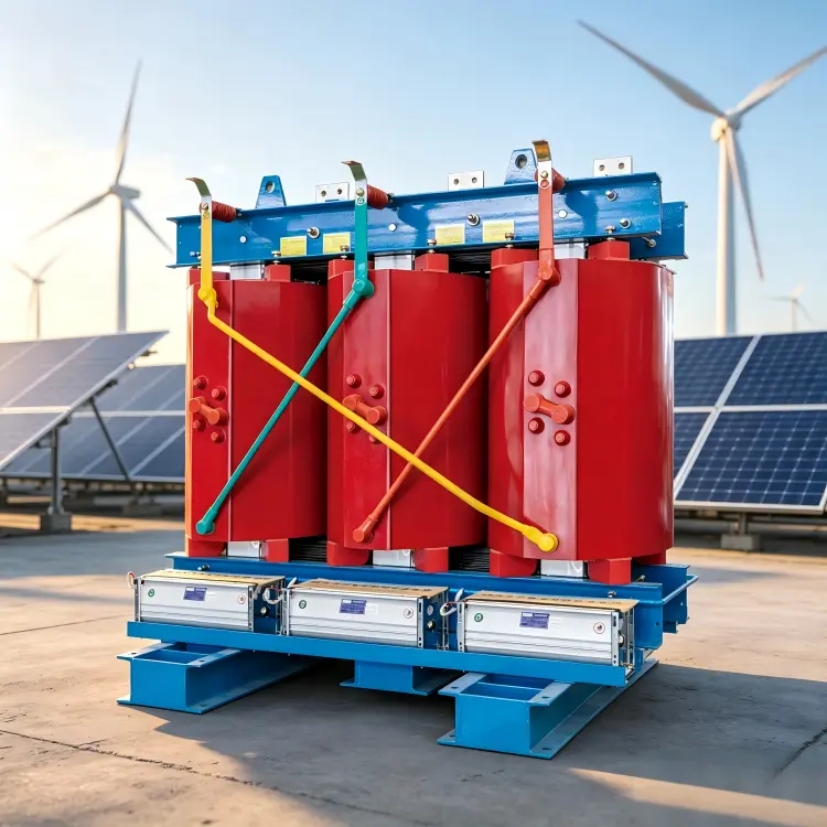
Oil-immersed units use an oil-paper composite insulation system with PCB-free mineral oil, and ester oil where the project is environmentally sensitive. Where oil is not acceptable, the transformer is supplied as a dry-type unit with epoxy cast-resin insulation.
The tank is fabricated from Q235 corrugated or plain plate and is fully sealed, with no conservator. Cooling is by oil circulation to the tank walls and radiators for oil-immersed units, or by air for dry-type units, with forced cooling applied where the rating requires it.
The enclosure is a double-layer sandwich construction in steel or composite board with a fireproof thermal-insulation filling and a rain-shed roof. Natural ventilation is combined with forced ventilation so that heat is rejected from the transformer room under full load.
The high voltage and low voltage rooms are fully separated, and the transformer is mounted externally or semi-externally so that its heat does not load the switchgear rooms. Door interlocks prevent access to a live compartment in service.
Porcelain or composite bushings are fitted for the high voltage connections, and the cables enter from below through a bottom entry with cable seals, which suits the buried cable practice used on most PV and wind sites.
Vector group Dyn11 is the common connection, with Ynd11 applied where the grid and earthing arrangement calls for it; the delta low voltage winding suppresses third harmonic currents. Off-circuit taps of plus or minus 2 x 2.5 percent are standard, and an on-load tap changer can be specified where the grid voltage moves during the day.
Base lifting lugs allow the complete unit to be lifted in one piece onto its foundation, and the footprint follows the factory datasheet. For coastal or offshore sites a C4 or C5 anti-corrosion coating system, silicone seals, anti-condensation heating and rodent-proof mesh are applied.
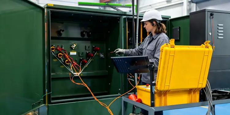
Every renewable energy transformer is routine tested as a transformer and, where the scope includes the enclosure and switchgear, function tested as a complete assembly before shipment.
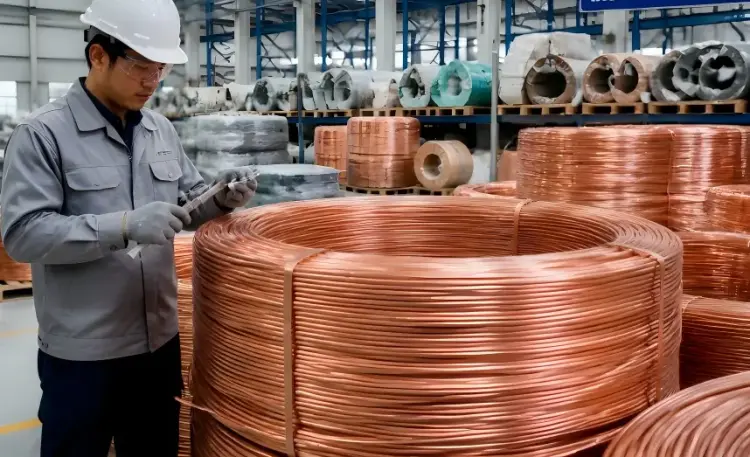
Core steel, foil and wire conductor, tank plate and insulating oil are inspected against the approved specification on receipt, and traceability records are kept for every batch used in the active part.
Winding, core stacking, tanking and oil filling are checked stage by stage, so that every Compact Substation for New-energy is verified against its design before it moves to final testing.
Routine testing follows IEC 60076 and covers winding resistance, ratio and vector group, no-load and load loss, impedance, insulation resistance, applied and induced voltage withstand, and oil tightness on sealed units. Where the supply includes the enclosure, the assembly is checked to IEC 62271-202 practice and against the applicable PV or wind grid-code requirements.
The unit is shipped with a routine test report and a certificate of conformity, recording the measured values against the nameplate data.
Compact Substation for New-energy is configured around the generation asset it serves: the inverter or turbine output voltage, the collection network voltage and the grid connection requirements come first, and the transformer, enclosure and protection follow from them.
Capacity is built from 1000 kVA to 3150 kVA and above, with higher ratings engineered for larger blocks. The high voltage side is normally 10 kV or 35 kV, and the low voltage side follows the inverter, typically 0.27 kV, 0.315 kV, 0.4 kV or 0.8 kV, with 0.8 kV used for large central inverters.
Cooling is oil-immersed ONAN or ONAF, or dry-type AN or AF where no oil is permitted. Insulation is oil-paper composite with mineral oil, or ester oil for environmentally sensitive projects; vector group Dyn11 or Ynd11, off-circuit taps or an on-load tap changer, CRGO Hi-B or amorphous core, and aluminium windings are all selectable.
For the enclosure and site conditions, the double-layer shell, compartment layout and C4 or C5 anti-corrosion coating are matched to the location, with silicone seals, anti-condensation heating and rodent-proof mesh for humid, coastal or desert sites.
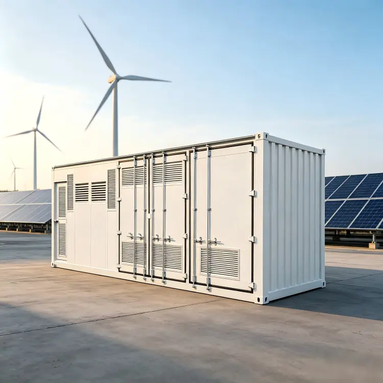
Renewable energy transformers are packed for long-distance transport to generation sites, which are often remote and have limited handling equipment on arrival.
Secure Packaging: Bushings, accessories and control cabinets are protected and braced against vibration and impact, and openings are sealed against moisture and dust.
One-piece Lifting: Base lifting lugs allow the complete assembly to be lifted in one piece, so no reassembly is needed at the site.
Reliable Transport: Road, rail or sea freight is arranged to the project schedule, with the route and handling method agreed for oversized units.
Complete Documentation: Routine test report, certificate of conformity, drawings, manuals and shipping documents travel with the unit.
Installation Support: Guidance on foundation, cable entry, earthing, protection settings and energisation is available through commissioning.
The vector group is chosen for the grid and earthing arrangement of the project, and for step-up duty it follows the low voltage winding configuration of the inverter, turbine or converter that feeds the unit. The connection applied to this unit is stated in the specification table.
The unit is routine tested before shipment and leaves the factory with the records that the project needs for commissioning and for the grid operator.
Cooling follows the transformer type selected for the site. Oil-immersed units use ONAN natural circulation, with ONAF fans added where the rating requires it, and dry-type units use AN natural or AF forced air cooling.


